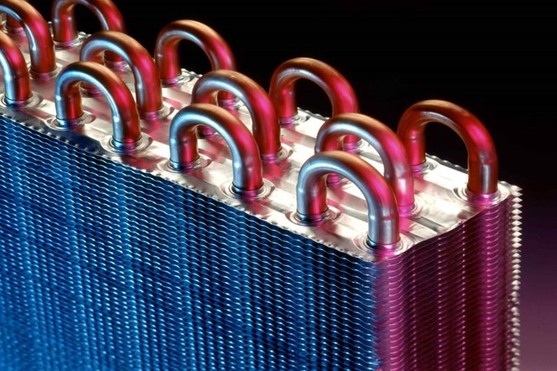
What’s the Heat Exchanger?
Heat exchangers are devices designed to transfer heat between two or more fluids—i.e. H. Liquids, vapors or gases – with different temperatures. Depending on the type of heat exchanger used, the heat transfer process can be gas-to-gas, liquid-to-gas, or liquid-to-liquid and can occur through a solids separator that prevents the liquids from mixing, or through direct liquid contact. Other design features, including building materials and components, heat transfer mechanisms, and flow configurations, also help classify and categorize the types of heat exchangers available. A diverse range of these heat exchange devices are used in a variety of industries and are designed and manufactured for use in both heating and cooling processes.
This article focuses on heat exchangers, examining the different designs and types available and explaining their respective functions and mechanisms. In addition, this article outlines the selection considerations and common applications for each type of heat exchange unit.
Thermodynamics of heat exchangers
The design of a heat exchanger is an exercise in thermodynamics, the science concerned with the flow of heat energy, temperature, and relationships with other forms of energy. To understand the thermodynamics of heat exchangers, a good starting point is to become familiar with the three modes of heat transfer – conduction, convection, and radiation. The following sections provide an overview of each of these heat transfer modes.
Management
Conduction is the transfer of thermal energy between materials that are in contact with each other. Temperature is a measure of the average kinetic energy of molecules in a material – warmer objects (those that have a higher temperature) exhibit more molecular motion. When a warmer object is brought into contact with a cooler object (one with a lower temperature), thermal energy transfer takes place between the two materials, with the cooler object receiving more energy and the warmer object receiving less energy. This process continues until thermal equilibrium is reached.
The rate at which thermal energy is transferred in a material by conduction is given by the following expression:

In this expression, Q represents the amount of heat transferred through the material in time t, ΔT is the temperature difference between one side of the material and the other (the thermal gradient), A is the cross-sectional area of the material, and d is the thickness of the materials. The constant k is called the thermal conductivity of the material and is a function of the intrinsic properties of the material and its structure. Air and other gases generally have low thermal conductivities, while nonmetallic solids have higher values and metallic solids generally have the highest values.
convection
Convection is the transfer of thermal energy from a surface by the movement of a heated fluid such as air or water. Most liquids expand when heated and therefore become less dense and rise relative to other parts of the liquid that are cooler. So when the air in a room is heated, it rises to the ceiling because it’s warmer and less dense, and transfers heat energy when it collides with the cooler air in the room, then becomes denser and falls back to the floor. This process creates a natural or free convection current. Convection can also occur by so-called forced or assisted convection, for example when heated water is pumped through a pipe, for example in a hot water heating system.
Design features of the heat exchanger
As stated above, all heat exchangers work on the same basic principles. However, these devices can be classified and categorized in a variety of ways based on their design features. Key characteristics by which heat exchangers can be categorized include:
flow configuration construction method heat transfer mechanism flow configuration
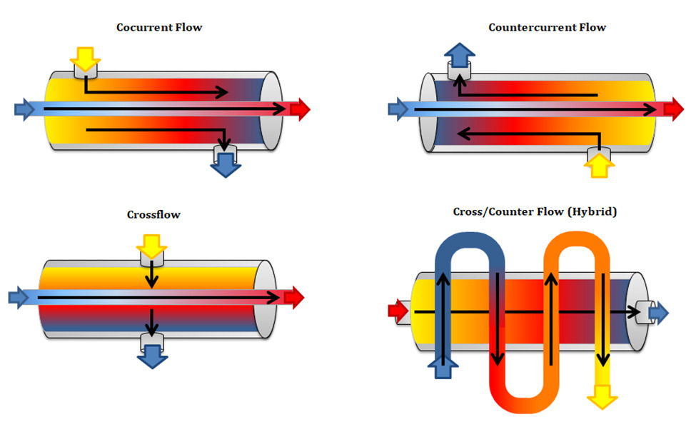
The flow form, also called flow arrangement, of a heat exchanger describes the direction of movement of the fluids within the heat exchanger relative to one another. There are four main flow configurations used by heat exchangers:
direct current countercurrent cross flow hybrid flow direct current flow
Co-current heat exchangers, also known as parallel flow heat exchangers, are heat exchange devices in which the fluids move parallel to each other and in the same direction. Although this configuration typically results in lower efficiencies than a counterflow arrangement, it also allows for the greatest thermal uniformity across the walls of the heat exchanger.
countercurrent flow
Counterflow heat exchangers, also known as counterflow heat exchangers, are designed so that the fluids within the heat exchanger move anti-parallel (i.e., parallel but in opposite directions) to one another. The most commonly used flow configuration, a counterflow arrangement, typically has the highest efficiencies because it allows for the greatest amount of heat transfer between fluids and, consequently,
the greatest thermal uniformity across the walls of the heat exchanger.
countercurrent flow
Counterflow heat exchangers, also known as counterflow heat exchangers, are designed so that the fluids within the heat exchanger move anti-parallel (i.e., parallel but in opposite directions) to one another. The most common flow configuration, a counterflow arrangement, typically has the highest efficiencies because it allows for the greatest amount of heat transfer between fluids and, consequently, the greatest temperature change.
cross flow
In cross-flow heat exchangers, liquids flow perpendicular to each other. The efficiencies of heat exchangers using this flow configuration are intermediate between those of counterflow and concurrent flow heat exchangers.
hybrid flow Hybrid flow heat exchangers exhibit some combination of the properties of the aforementioned flow configurations. For example, heat exchanger designs can utilize multiple flow passages and configurations (e.g., both counterflow and crossflow configurations) within a single heat exchanger. These types of heat exchangers are typically used to accommodate the constraints of an application such as: B. space, budget costs or temperature and pressure requirements.
Figure 1 below shows the different flow configurations available, including a cross/counterflow configuration which is an example of a hybrid flow configuration.
construction method
While the previous section categorized heat exchangers based on the type of flow configuration used, in this section they are categorized based on their construction. Design features by which these devices can be classified include:
Restorative vs. regenerative
Direct vs Indirect
Static vs. dynamic
Type of components and materials used
Recuperative vs. Regenerative
Heat exchangers can be divided into recuperative heat exchangers and regenerative heat exchangers.
The difference between recuperative and regenerative heat exchanger systems is that in recuperative heat exchangers (commonly referred to as recuperators), each fluid flows simultaneously through its own channel within the heat exchanger. In contrast, regenerative heat exchangers, also known as capacitive heat exchangers or regenerators, alternately allow warmer and colder fluids to flow through the same channel. Both recuperators and regenerators can be further divided into different categories of exchangers, such as direct or indirect, static or dynamic. Of the two types indicated, recuperative heat exchangers are more widely used throughout industry.
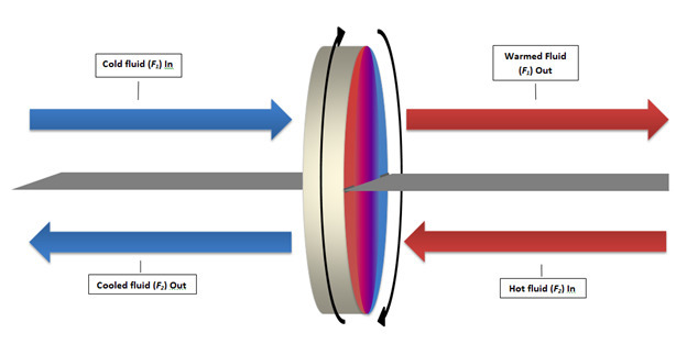
In an example of the static type, warmer fluid is passed through one channel while cooler fluid flows through another for a fixed period of time, at the end of which through the use of fast acting valves the flow is reversed so that the two fluids switch channels. An example of the dynamic type typically uses a rotating, thermally conductive component (e.g., a drum) through which warmer and cooler fluids continuously flow—albeit in separate, sealed sections. As the component rotates, any given section alternately traverses the warmer vapor and cooler streams, allowing the component to absorb heat from the warmer fluid and transfer the heat to the cooler fluid as it passes. Figure 2 below shows the heat transfer process within a rotary type regenerator with a counter flow configuration.
Components and materials of heat exchangers
There are different types of components that can be used in heat exchangers, as well as a wide range of materials used in their construction. The components and materials used depend on the type of heat exchanger and its purpose.
Some of the most common components used to build heat exchangers include shells, tubes, coiled tubing (coils), plates, fins, and adiabatic wheels. For more details on how these components work in a heat exchanger, see the next section (see Types of Heat Exchangers).
While metals are very suitable for the construction of heat exchangers due to their high thermal conductivity and are widely used, as in the case of copper, titanium and stainless steel heat exchangers, other materials such as graphite, ceramics, composites or plastics can be used depending on the needs of the Heat transfer application provide greater benefits.
Figure 3 – Classification of heat exchangers by design
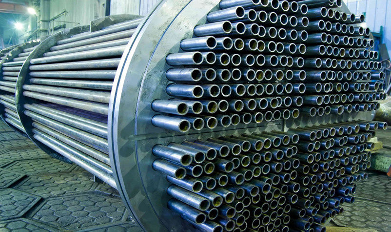
shell and tube heat exchanger
The most common type of heat exchanger, shell and tube heat exchangers, are constructed from a single tube or a series of parallel tubes (i.e., tube bundle) enclosed in a sealed, cylindrical pressure vessel (i.e., shell). The design of these devices is such that one fluid flows through the smaller tube(s) and the other fluid flows around its outside(s) and between them within the sealed envelope. Other design features available for this type of heat exchanger include finned tubes, single or two phase heat transfer, counterflow, cocurrent, or crossflow arrangements, and single, two, or multiple pass configurations.
Some of the types of shell and tube heat exchangers available include spiral heat exchangers and double tube heat exchangers, and some of the applications include preheating, oil cooling and steam generation.
double pipe heat exchanger
Double tube heat exchangers are a form of shell and tube heat exchanger and use the simplest heat exchanger design and configuration, consisting of two or more concentric, cylindrical tubes or tubes (one larger tube and one or more smaller tubes). According to the shell and tube heat exchanger design, one fluid flows through the smaller tube(s) and the other fluid flows around the smaller tube(s) inside the larger tube.
The design requirements of twin tube heat exchangers include characteristics of the previously mentioned recuperative and indirect contact types, as the fluids remain separate and flow through their own channels throughout the heat transfer process. However, there is some flexibility in the design of double tube heat exchangers as they can be constructed with cocurrent or counterflow arrangements and used modularly in series, parallel or series-parallel configurations within a system. For example, Figure 4 below shows heat transfer within an insulated double-tube heat exchanger in co-current configuration.
Wilson Pipeline is a leading manufacturer and distributor of flange fittings material from alloy steel stainless steel to carbon steel.products, including Super Duplex Stainless Steel Flanges, Stainless Steel Flanges, Stainless Steel Pipe Fittings. ASME B16.5 ASME B16.9 ASME B16.11 EN1092,ANSI ASTM,GOST,JIS,DINWilson Pipeline products are widely used in Shipbuilding, Nuclear power, Marine engineering, Petroleum, Chemical, Mining, Sewage treatment, Natural gas and Pressure vessels and other industries.If you want to have more information you want to share your enquiry with us, contact us at sales@wilsonpipeline.com


